USB Audio Interface

Table of Contents
For a long time I’d wanted to make an audio interface for recording music and voice calls on my computer. It seemed like the ideal next step from making analog guitar effects pedals and some small microcontroller projects. I finally had the perfect opportunity in my last semester during the course CSE 145: Embedded Systems Design Project. The course is long over by the time I’ve gotten around to writing this post, but I’m happy to report that I still use this interface daily.
Background⌗
The below sections detail some general information I gathered for this design. Hopefully it can be useful to others starting on audio electronics.
Difference between audio sources⌗
All analog audio sources function by oscillating a voltage or a current to represent sound. However, the specific differences between different types of sources requires consideration and in some cases special handling from the perspective of amplifier design. For the purposes of an audio interface, there are several categories which we are concerned with:
- Dynamic microphones
- Condenser microphones
- Pickup instruments
- Line-level audio
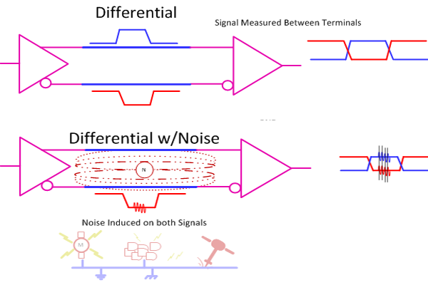
These can be grouped into the coarser categories of balanced and unbalanced audio, with the microphones generally being balanced, and the other two unbalanced. “Balanced” audio refers to the fact that these sources use cables in which both the negative and positive signal wires are near-identical in construction, with shielding connected to ground. This topology ensures that any interference along the cable length - either from capacitive coupling or EM sources - applies equally to both polarities. This “common-mode” interference can then be eliminated by a differential amplifier on the receiving end of the cable. The concept is well illustrated by the diagram from Hackaday below. On the other hand, unbalanced audio references the positive signal to ground, by connecting the shielding to the negative terminal on the source side, and to ground on the receiving side. The shielding still provides some resistance to interference, and these sources can be used with standard amplifiers. Microphones generally use balanced cables due to the low signal levels present on their output, though this is not as much of a concern for pickup instruments or line-level audio. The prototypical balanced cable for audio purposes is the XLR cable, which has three terminals for positive, negative, and ground.
Dynamic microphones are a class of microphone that approximately functions as a speaker cone in reverse. There is a sealed diaphragm which is mechanically attached to an electromagnet. Changing pressure in the air causes the diaphragm to move, which then generates electric current by moving the electromagnet relative to a permanent magnet installed in the microphone. These sources have low sensitivity but also low impedance, on the order of 100 ohms. However, due to the inductive nature of the source, the preamplifier needs a comparatively large input impedance to avoid affecting the frequency response. These microphones have low sensitivity but are also inexpensive, making them very popular for recording instrument amplifiers and drums.
Condenser microphones function by a different mechanism. They form a capacitor from a thin metallic membrane and a stationary plate. Changing sound pressure causes this membrane to move, which alters the capacitance, generating a current. This topology is very high impedance, and also requires an external bias voltage to function, where 48 volts is the industry standard level. In order to lessen the difficulties with interfacing with high impedance sources, many condenser microphones contain an integrated FET for impedance matching, which is powered off the bias voltage. Condenser microphones are far more sensitive than dynamic microphones, and are common for recording voices. These are an extremely common type of microphone, but were not supported for this project due to the additional technical challenges associated with generating and exposing 48 volts.
Pickup instruments generate voltages based on the movements of metallic strings or tines next to an electromagnet, or from the compression of a piezoelectric material attached to a vibrating surface. Usually these transducers are referenced to ground, leading to an unbalanced audio source as discussed above. These sources are also low impedance, but must be matched with a high-impedance amplifier to preserve the frequency response. The standard connector for these types of sources is a 1/4" TS cable, and they are found in most electronic string instruments, and some drum microphones.
Lastly, line-level audio is an term which represents audio sources that are already amplified up to working voltages and currents. The range varies, but generally line-level sources have a maximum amplitude of approximately one volt. This is the easiest type of source to interface with, as no amplification or impedance matching is necessary before digitizing.
USB Audio⌗
One of the major advantages of USB is the device class system. This part of the specification defines a standard set of types of devices and their associated sub-protocols. For example, there are device classes for mass storage, human interface devices (such as mice and keyboards), printers, cameras, and hundreds of others. These classes cover the majority of use cases for USB. If a device is compliant with the device class specification, then it will generally work with any host operating system, making significantly less work for host driver implementers and device creators. This “plug-and-play” nature of USB devices is one of the major selling points of the standard, and has led to its wide adoption.
One of the device classes called USB Audio Device Class 2.0 (UAC) supports a wide variety of audio peripherals. By designing an audio interface to comply with this standard, no host drivers need to be written, and the device should seamlessly function with any host configuration.
There are several different transaction types defined in the USB standard: control, interrupt, isochronous, and bulk. Each transaction type is suited for a different use case, and isochronous transfers are specifically tailored for streaming applications. For the purposes of creating an audio interface, these and control transfers are the only necessary types. Isochronous endpoints are special in that they do not have any error checking or re-transmission in the protocol. This ensures the minimum latency possible, which is critically important for audio applications.
Analog-Digital Conversion⌗
The most important aspect of an audio interface is the conversion from analog to digital with the smallest amount of distortion or noise. Generally this is done using a discrete integrated circuit (IC) that continuously samples the analog lines and outputs digital representations. There are several architectures for ADCs, with the most common being successive approximation register (SAR) and delta-sigma. These two architectures have vastly different internal structures and methods of operation, the specifics of which are out of scope, but this article by Analog has some good info. It suffices to say that delta-sigma ADCs are more common for audio applications, because of higher bit resolutions and less stringent anti-aliasing requirements.
Irrespective of architecture, there are two primary design considerations for using ADCs. One is that ADCs generally have a low input impedance, and require a substantial amount of current from the previous analog stage. Even if the signal is already at the correct line level, a buffer is still required to drive the ADC inputs. The second is that high-frequency content will be aliased back into the frequency range of interest after digitization, usually appearing as noise. Therefore, it is important to have a low-pass anti-aliasing filter before signals enter the ADC. For audio purposes the range of interest is 20Hz to 20kHz, with a sampling frequency of 44.1 or 48kHz, so the -3dB point of the filter is usually placed between 20-40kHz.
Design⌗
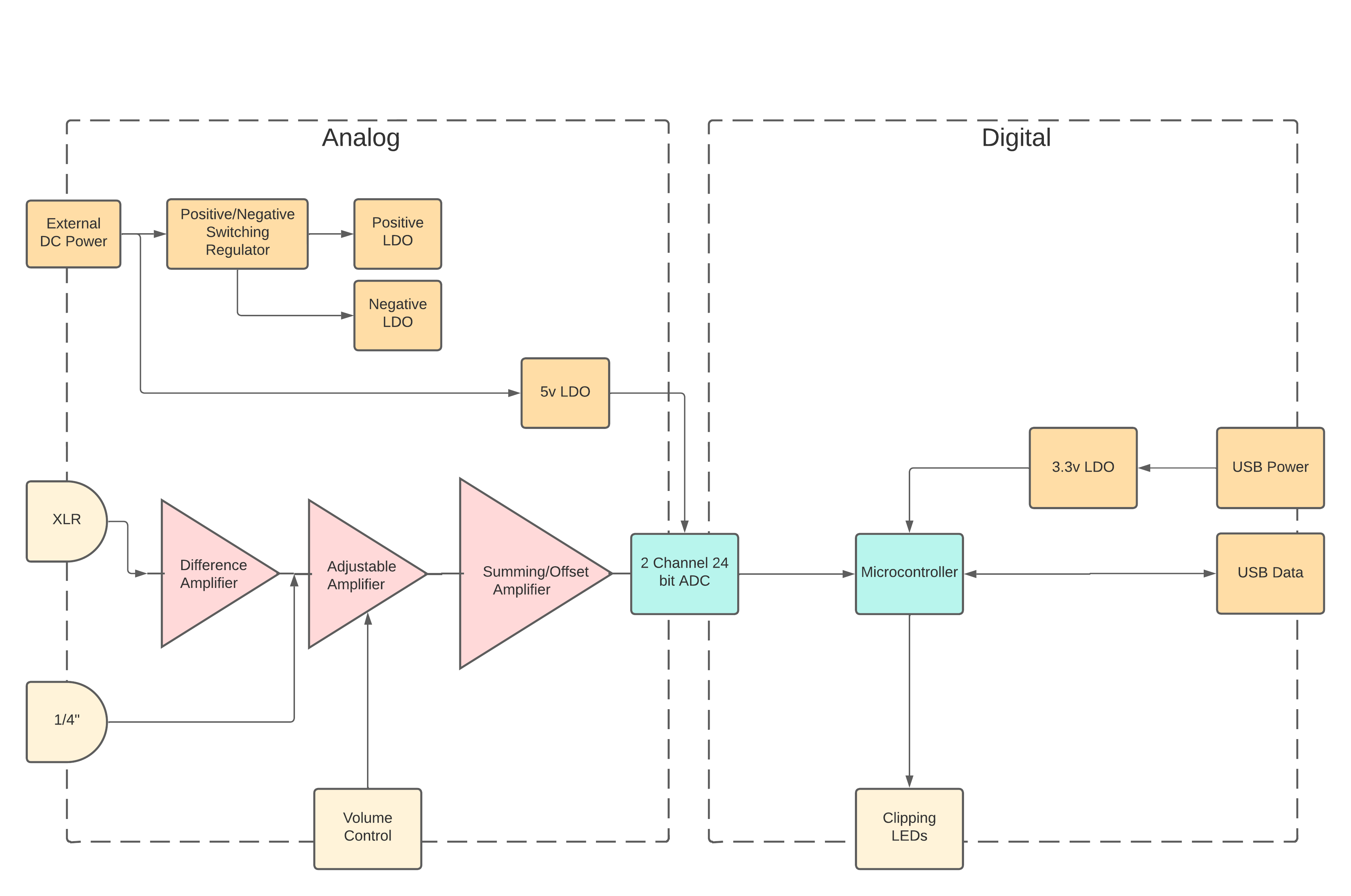
The systems diagram below describes the amplifier stages and power tree based upon the above considerations. The external voltage rail is assumed to be noisy, and the negative rail will contain switching noise. Therefore both are isolated from the analog supply by an LDO (low-dropout linear regulator). The balanced XLR input has an additional difference amplifier to provide additional gain as well as eliminating the common-mode interference. Both channels pass through single-ended adjustable amplifiers, where external potentiometers adjust the gain. The summing amplifier adjusts the DC bias level to bring the full wavelength above zero volts, in order to bring the input to a safe level for the ADC. This ADC is attached to a USB-supporting microcontroller which passes the data to the host. The specific details of electrical, firmware, and mechanical design which enable this system are described in the following sections.
Electrical⌗
The electrical design of this audio interface can be broken into three separate categories: analog, digital, and power. For analog, the primary considerations are providing enough gain, and reducing the amount of noise. The microphone used for testing this project was the Shure SM57, an extremely common and prototypical dynamic microphone. According to the specifications, this microphone has a sensitivity of 56mV/Pa. A more familiar metric would be that a standard speaking volume of 55dB SPL produces an output of 0.6mV. Therefore approximately 80dB of gain would be sufficient for the XLR signal path. This was split evenly across the differential and adjustable stages. For the instrument input, a unity gain is necessary to support line-level audio, and an electric guitar pickup produces approximately 100mVpp output. For consistency, both adjustable stages were designed for 40dB maximum gain and 0dB minimum gain.
In amplifier design, the intrinsic thermal noise generated by resistors can be a significant contributor to the overall noise profile. This thermal noise has a voltage that is linearly proportional to heat as well as resistance. Therefore, it is best practice to reduce the resistances used in the amplifier feedback loop and filters to the minimum level without loading the op-amps. This is especially important for the resistors in the difference amplifier, since the signal amplitudes are very low at this stage. The higher currents resulting from this choice have an additional noise benefit, as it reduces the effect of shot noise as well as capacitively or inductively coupled noise from the environment. The amplifiers were constructed with 4 TI OPA2134 op-amps, which were chosen for low noise and high power supply rejection ratio (PSRR).
The digital design of the interface hinged on the choice of microcontroller and ADC. For the microcontroller, the STM32F042 was chosen due to the hand-solderable package, USB support, and price. In addition this microcontroller had an I2S peripheral for interfacing with the ADC. The ADC chosen was the TI PCM4202, which provided two channels at 24 bits each, and a total harmonic distortion + noise (THD+N) of -105dB. This ADC is designed specifically for audio purposes, which brings several important features such as DC bias removal through an internal digital high-pass filter.
Delivering power to all these components required multiple different voltage rails. All op-amps were powered off the linearly regulated +7v and -7v rails, generated from low-noise LDOs. The negative voltage were generated by a switching regulator in Cuk configuration, again to reduce noise. The analog and digital 5v and 3.3v rails were both generated with higher-power LDOs. Usually a digital rail would be generated with another switching regulator, but a linear regulator was chosen to reduce to total amount of switching noise on the board, as well as reduce design complexity. In a future redesign I’d like to power everything through USB, and in that case the higher efficiency of the swtiching regulator would trade more favorably.
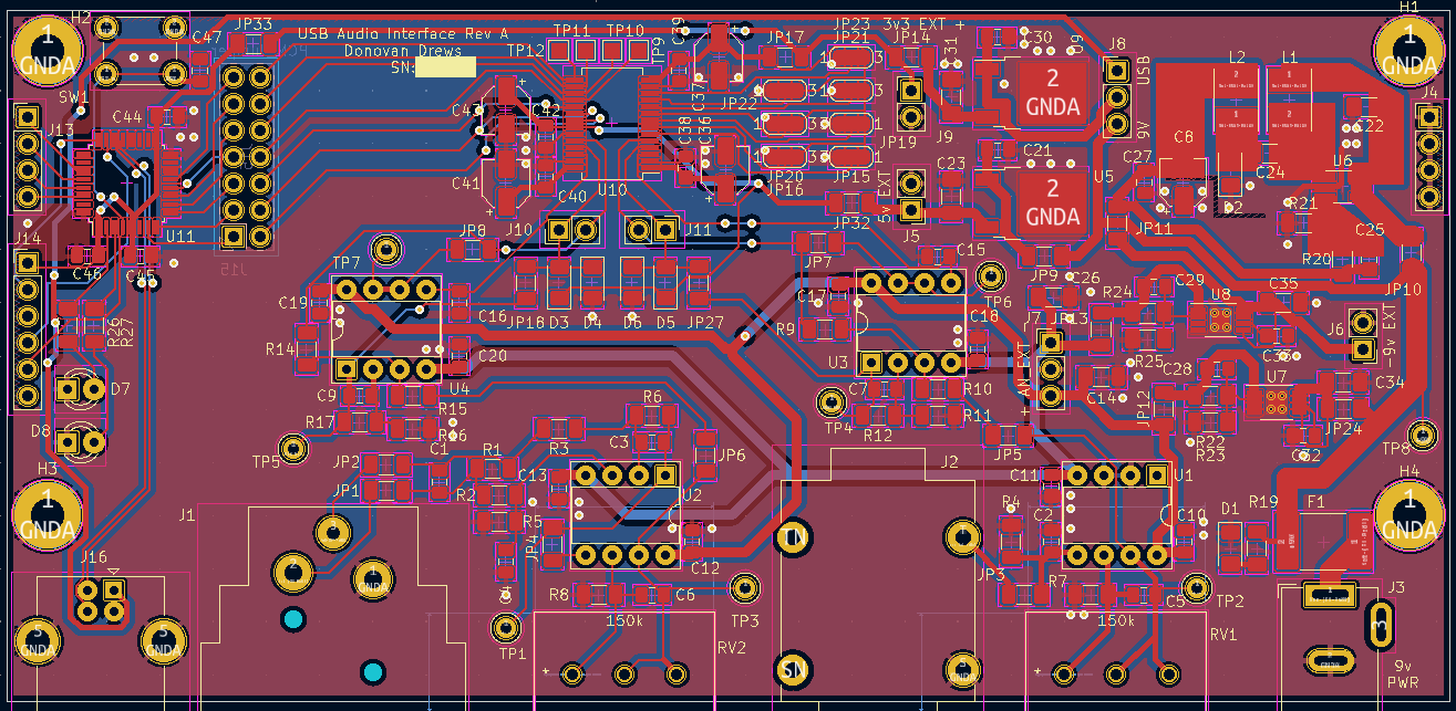
The high-level layout of the printed circuit board (PCB) brought all connectors to the front edge to simplify mechanical design. In addition, digital and switching circuitry was spatially isolated from sensitive analog circuitry, as can be seen in the layout below. A significant number of test points and jumpers were added to aid testing and verification of the board after assembly.
Firmware⌗
The firmware running on the microcontroller has 3 main tasks:
- Gather samples from the ADC, and move them into USB packets for transmission to the host.
- Handle USB control and enumeration signals.
- Control the clipping LEDs.
The first of these tasks is accomplished through the use of the I2S peripheral and direct memory access module (DMA). The I2S peripheral generates control signals for the ADC and receives the samples in a bit-serial fashion. The DMA is then configured to move these samples into a circular buffer located in main memory upon each reception. This circular buffer is the hand-off point to the USB side of the firmware stack.
The tinyUSB library was used to implement most of the USB functionality. This is a middleware library that abstracts hardware-specific USB functionality into a generalized software API. USB device, configuration, and endpoint descriptors were created and made accessible to the host through tinyUSB. These allow the host to determine the name, manufacturer, device class, and specific audio attributes of the interface. Isochronous endpoint support in not included in the driver for stm32 in tinyUSB, so support for this endpoint and transfer type was added to a local fork of the library. I am hoping to upstream this change but have not found the time as of yet.
After each 1ms USB frame, the last millisecond of audio data is parsed in the circular buffer to determine if the clipping threshold has been exceeded, and to fix endianness issues created by the DMA copying. If the audio is clipping, the LED is turned on for the next 200ms to notify the user. This parsed data is then moved into a tinyUSB FIFO, where it is eventually placed into the stm32’s packet buffer memory region. On the stm32 architecture, isochronous endpoints use double buffering to achieve maximum throughput for streaming applications such as audio.
Mechanical⌗
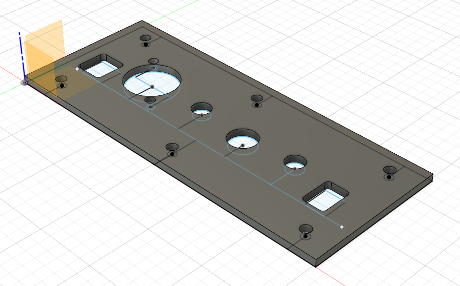
An enclosure for the PCB is essential to prevent both mechanical damage as well as ESD. The primary consideration in the mechanical layout was ease of assembly and disassembly. For this reason, all connectors are attached to only the front plate of the enclosure, so that the PCB can be entirely removed by only removing one face of the enclosure. In this same vein, the front and back plates are connected with M3 hex bolts to allow for many cycles of attachment and detachment without mechanical failure. For durability the sides of the enclosure are constructed with 1/4" oak boards, and the front and back plates with 1/8" brushed aluminum sheet metal. Both front and back plates were modeled in the CAD program Fusion360 before being CNC routed and attached to the wooden side panels, as seen in the cover image.
Results⌗
SNR measures the ratio of the difference in amplitude between the signal when at full scale, and the noise floor. It is a common way of measuring the amount of useful information that can be derived from a signal. Usually, the measurement is specified in dB and has an associated bandwidth over which the noise is collected. For audio, this band is assumed to be 20Hz-20kHz. However, this is a poor proxy for audio quality, as many other effects can lead to audible degradation, such as distortion. Total harmonic distortion (THD) is another measurement that quantifies the amount of distortion in a signal. The measurement is performed by inputting a sinusoid of a known frequency into a system, and then recording the output. Then, Fourier analysis is used to compare the power present in the fundamental frequency as opposed to the sum of all integer harmonics of that frequency. This is a very common measurement in power electronics, RF engineering, and amplifier design.
One of the most useful measurements of audio quality combines these two metrics into “total harmonic distortion and noise” or (THD + N). Sometimes it is also referred to in the inverse ratio form as “signal to noise and distortion ratio” (SINAD). This is performed by inputting a sinusoid into the system, and then applying a notch filter at that frequency to the output. The ratio between the total power in the unfiltered and filtered signals is the SINAD, and is a good proxy for the audible quality of the system. In order to provide a closer representation of perceptible audio quality, sometimes “A-weighting” is applied to the output, which scales the power at each frequency based on the perceived loudness by the human ear. Generally, this means attenuating the very high and very low frequencies, while amplifying the mid-range. For the purposes of this project, SINAD is used as the primary measurement of quality, but without A-weighting.
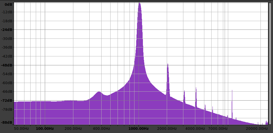
The audio interface was measured to have a SINAD of 45dB on the instrument channel and 27dB on the microphone channel. When viewing the frequency plot for the instrument input below, it can be seen that most of the SINAD reduction is due to the harmonic distortion and not the noise. These measurements fall short of the specification, and there are several theories as to the cause. One of the most likely candidates for the poor performance of the microphone input centers around the crosstalk between channels, which is approximately 30dB. When the instrument input is floating, the high impedance source amplifies EMI to nearly full-scale, and this carries over to the microphone input during testing. A fix was applied to resolve this issue, but additional testing did not take place after this change was made. Another possible cause for both channels is the mismatch between the real and expected ADC sampling frequency, which is 46.7kHz as opposed to 48kHz. This means the OS must pick up the slack of interpolating these samples, which could lead to all sorts of hidden issues.
Future⌗
This project went more seamlessly than I had expected, but there is still a lot I would like to improve on in a future revision. High on the list is adding support for condenser microphones, as they are the most commonly used for high-precision recordings. In the last year of use I have also noticed an occasional clicking noise, which I think can be attributed to the sampling rate issue above. Powering entirely off of the USB Vbus would also improve the usability significantly.
Here’s a demo created by a good friend of mine who used the interface to record electric bass, drums, and Rhodes piano to demonstrate the audio quality. (We accidentally left the metronome in!)