Remote Control Car

The goal of this project was to create a small and simple RC car using only materials that were on hand. While most RC devices are operated off a radio transmitter and receiver running directly into a motor controller, I opted for a more standard robotics approach of using an on-board computer (specifically a Raspberry Pi 2). This would then have a Wi-Fi dongle where it can communicate with a controlling computer with a gamepad for driving controls. Having an OBC also makes running a video feed significantly easier.
The first step was to assemble the mechanical side of the car. I did not have any motors on hand, but luckily an old, broken stereo had a CD read head with a sufficiently powerful motor and gearing. Bending and cutting this read head assembly, and adding a wire coat hanger as an axle, provided a workable drive assembly.
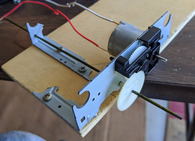
As seen in the title image, I cut some wooden wheels out of plywood and attached a servo motor with the front axle. Lots of the work could have been cleaner, but it is a functional base for adding tech on top.
Moving onto the electrical side, the Raspberry Pi GPIO cannot source enough current to power the motor nor the servo. Therefore, a power board is required to control these peripherals. The only power source I have on hand is 9 volt batteries, but the motor and the servo both require 5 volts to operate within specification. Thankfully, I had a single L7805 linear regulator around to use for this conversion. A linear regulator is not the ideal choice for this application, but it would be functional with enough cooling.
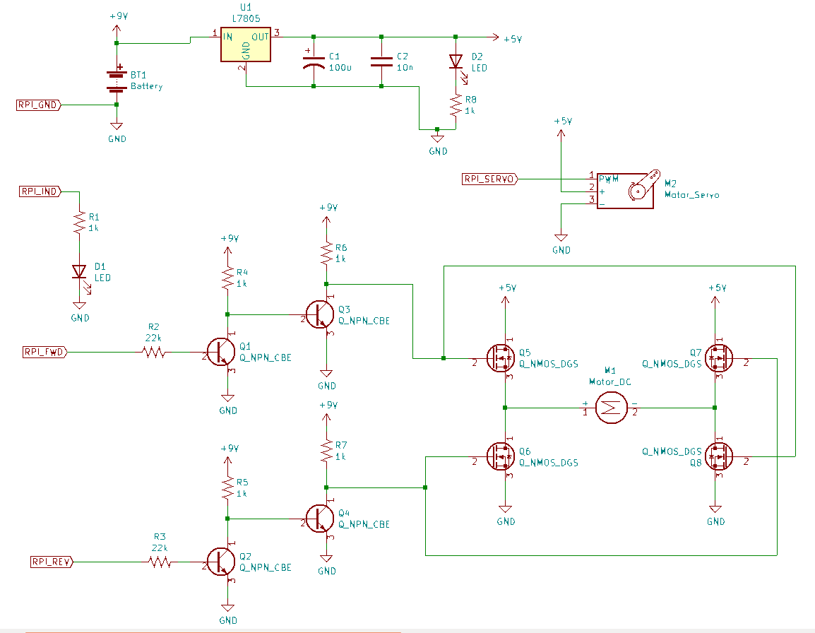
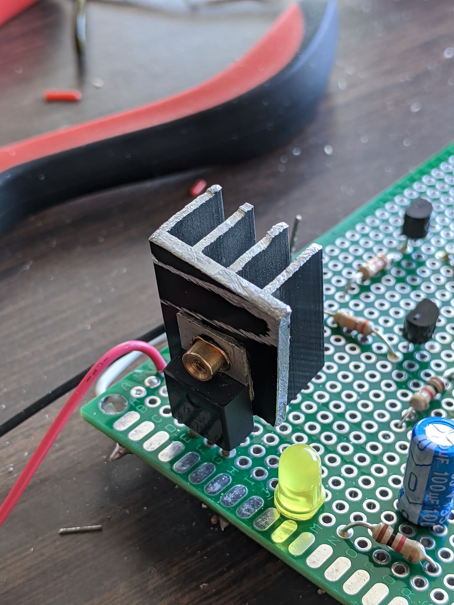
The above schematic is, to my knowledge, a commonplace implementation of this scheme. The motors are controlled through an H-bridge, using the body diodes of the MOSFETs to handle inductive flyback. The 3.3v logic level of the Raspberry Pi is not sufficient to put the FETs into full conduction, so two inverting NPN switches are used in series for each input (a single FET each would have been better, but I didn’t have any extras). The 5v power rail has two smoothing capacitors to handle low and high frequency ripple along with an LED to indicate power. The servo is connected to the 5v rail and a Raspberry Pi pin. Lastly an indicator LED is in place, that I’ll likely use to show Wi-Fi connection in the future. The design was first tested on a breadboard, and later moved to a perfboard. In order to control heat dissipation from the regulator, part of an old GPU heatsink was cut off and attached.
As with anything electrical, I always fear some oversight or edge case not considered, but this board seems to be functional for the time being. Once I learn more about electronics, I may change the design entirely.
The last part I implemented was the software. It seemed that just some simple python scripts should be up to the task. I attached an unused Logitech C720 webcam to one of the host USB ports on the Pi. Using OpenCV, images are captured from the camera, resized to 480p, and encoded into a JPEG format. A TCP connection is established with the control computer using python sockets, and each image is sent independently over this link. On the control side, the images are decoded and displayed. The latency of this setup is suboptimal - around 250ms - due to both the inherent latency of the C720 and the time taken to encode each image (about 70ms). Certainly gains could be had by using GPU image compression, or even a dedicated video format like H.264. However, in this situation I felt that the current setup provided adequate performance to make the additional complexity not worthwhile.
In another python thread, the control computer receives events from a USB gamepad and translates them into power and steering values before sending them over the same TCP port to the on board computer. Originally I used the gpiozero library for outputting the PWM signals, but realized that this did not take advantage of the existing PWM hardware and used a software emulation instead. An oscilloscope revealed that the accuracy of the pulse widths was inadequate, especially on the servo line. After some searching, I switched to the pigpio library which allows use of the hardware PWM, and the issue was resolved.
After the mechanical, electrical, and software components were completed, I realized that I did not have a Wi-Fi dongle and that the servo I had installed was broken. Originally I had also planned to power the Raspberry Pi from the power board, but the L7805 was unable to supply enough stable current for reliable operation. A cellphone “power bank” was able to fix this issue, but overall the car was not able to be completed due to the other issues. Below is the current state of the car; it has the motor control and video feed operational.
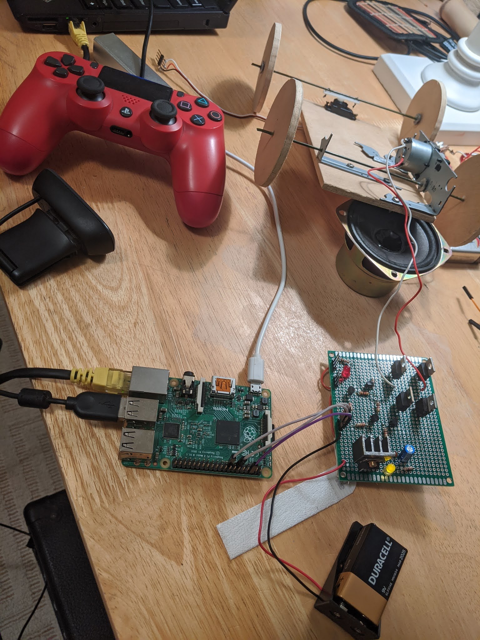
Hopefully in the future I can obtain these last two parts and install all the boards onto the chassis. For the time being, the project is a proof of concept with most of the desired functionality. When the project is completed, this post will be updated.